Autodetection Markers
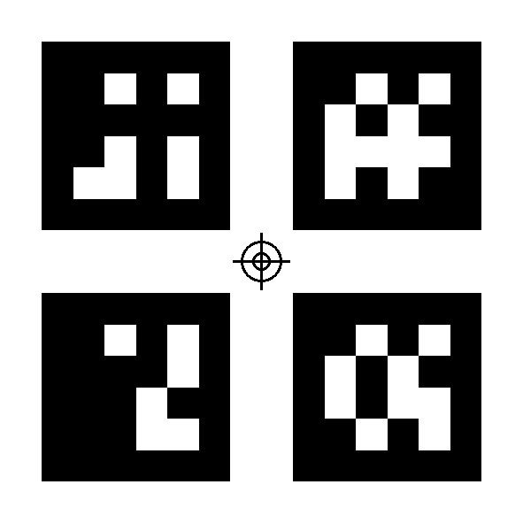
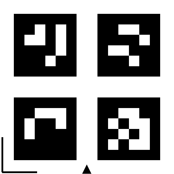
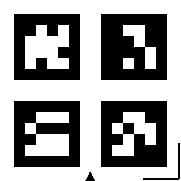
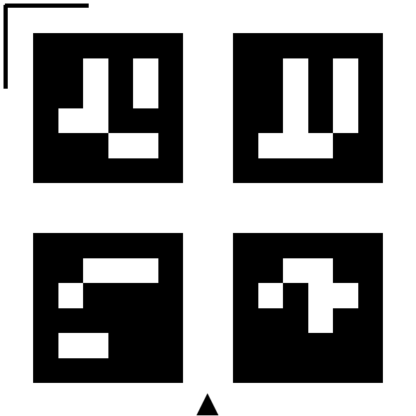
Markers can be used for offcut autodetection or autoengrave in Dekupeo. They help to determine the scale, origin, and machine axes from the uploaded image of the workbed. Each Dekupeo marker is a specific combination of 4 ArUco tags (~QR codes for machine vision).
Marker Download
You can download Dekupeo markers from the following links:
- A4 - All Markers for printing
- Letter - All Markers for printing
- Zero Plate (Origin) 50 mm marker - defines the origin (0,0) of the workbed
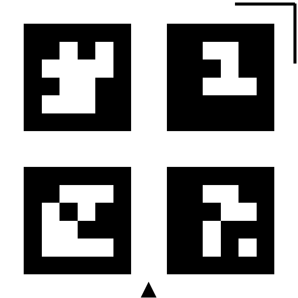
- Scale markers - define scale reference with 30, 50 or 100 mm size
- Corner markers - define machine axes and 50 mm scale reference
Marker Preparation
You can print the markers on a standard paper using a regular printer or create them directly using your laser cutter.
Printing on Paper
Print the markers, cut them out and glue them to pieces of plywood, so that their top surface is flush with the material surface when placed in workbed.
Creating markers with Laser Cutter
You can also create the markers directly using your laser cutter. Define square with dimensions for the marker, attach the marker file as raster data and cut and engrave them from plywood. Markers can have the same color as detected material, because marker area is excluded from the search.
Marker Usage
You can use no marker or several markers in a single setup.
- Scale – Check that the dimensions of the markers match the intended size.
- Good lighting – Ensure proper lighting conditions (no shadows, no glare).
- Keep camera flat – Position the camera perpendicular to the work surface for minimal distortion.
- Level with work surface – Ensure the markers are level with the material surface.
Possible marker setups:
- No markers
Define origin and scale manually. - 2 corner markers (BL + BR, TL + TR, BL + TL or BR + TR)
The system will recognize direction of marked axis and scale, because the corner marker serves as a 50 mm scale marker as well. The other axis will be defined as perpendicular. Origin will be defined as the axes intersection point + offset defined in settings. In this way, the machine can home to the origin if offsets are set properly. - 3 or 4 corner markers
The same functionality as with 2 corner markers, but with better accuracy of axes recognition and scale detection. - Corner markers + Zero plate
The zero plate provides a reference for the origin. You move the laser on the center of the zero plate and set it as the origin to align the SW coordinates with the machine coordinates. - Additional Scale markers
For each setup, you can add additional scale markers to improve scale detection accuracy. The system will automatically detect them and use for scale calculation together with corner markers.